Simplify your product management process with product lifecycle management software. Enhance collaboration, data accuracy, and streamline the product lifecycle.
Our Product Lifecycle Management (PLM) software combines product information from start to finish, including design, manufacturing, service, and disposal. It uses methods, processes, and structures along with IT systems to manage data effectively.
Centralized Data Management
Product Data Management (PDM) has advanced to PLM for a centralized product information source, providing stakeholders with up-to-date data access.
Digital Information Twin
The team of engineers provides data for each process stage and shares lifecycle data with the product engineering team. The information is utilized to generate a digital replica connecting product specifications, establishing digital threads for monitoring and modifications throughout the product’s lifespan.
Collaboration Tools
Facilitate communication and collaboration across different departments and geographical locations.
Version Control
Tracking changes and keeping a history of revisions ensures accuracy, compliance, and transparency. It helps trace modifications, avoid errors, and maintain accountability. This is essential for effective collaboration and document management.
Workflow Automation
Automating routine tasks boosts efficiency and reduces mistakes. It frees employees for strategic work, streamlines workflows, and cuts human error, leading to higher productivity and quality. Embracing automation helps businesses stay competitive.
Regulatory Compliance
Ensuring products meet industry standards and regulations guarantees safety, quality, and legality. This involves thorough testing, certification, and documentation. Non-compliance can lead to recalls, fines, and reputational damage. Regulatory compliance maintains consumer trust and avoids legal issues.
Ensure that products meet industry standards and regulatory requirements.
Benefits of PLM, the Pathway to Digital Products
As more products include software and electronics requirements, the need for flexibility, agility, and variant management increases. These factors drive digital engineering and product management, from product engineering to operations, making forward-thinking product lifecycle management software a must.
Improved collaboration: Leverage product lifecycle management software to bring together your Computer Aided Design (CAD) data, documents, and Bills of Materials (BOMs) with a product data backbone. The controlled workflow gives team members in production, purchasing, marketing, and other departments early access to current product data.
Increased efficiency: Automation of workflows and processes reduces manual effort and the potential for errors, leading to increased productivity.
Cost savings: By optimizing processes and reducing waste, product lifecycle management software can lead to significant cost savings over the product lifecycle.
Enhanced quality: With robust data management and version control, product lifecycle management ensures higher quality and consistency in product development.
Regulatory compliance: PLM software can help maintain compliance with industry standards and regulations, reducing the risk of non-compliance penalties.
Global support: Rely on our global support team for help, no matter where you and your team are.
Revision security: Protectable files can’t be overwritten. Also, the entire history of an initiated change is logged so you can see when it was made and who made it.
Revalize Standard Implementation Method (RSIM): This approach allows us to easily set up our Product Lifecycle Management software on your end with minimal customization, simplifying future updates for you to handle.
Product Lifecycle Management — it’s all about gradually capturing and electronically managing our processes and the data created throughout them across the entire product lifecycle. This approach has really helped us a great deal.”
Martin Rydzy
Application Manager, BRITA GmbH
Product Lifecycle Management Software
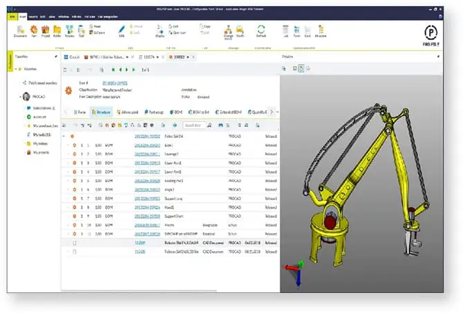
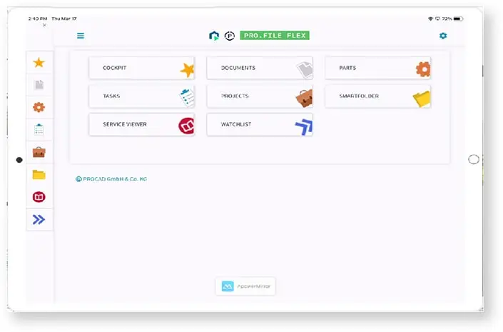
PRO.FILE PLM and keytech PLM, both powerful software solutions, integrate with other enterprise systems.
PRO.FILE blends seamlessly with many systems, providing a comprehensive platform for managing product data and processes. Key features include:
Document management: Effectively handle product documents by integrating multiple CAD systems, connecting ERP with our technology, and easily expanding PRO.FILE using system APIs.
Change management: Streamline the process of implementing changes to products.
BOM management:Maintain accurate BOMs to ensure product accuracy.
Keytech is known for its flexibility and scalability. It supports a wide range of industries and provides advanced features, such as:
Project management: Plan and manage projects effectively with integrated tools.
Quality management: Ensure product quality with comprehensive quality management capabilities.
Supplier management: Manage supplier relationships and ensure the timely delivery of components.
Seamless integration: Integrate keytech PLM into different authoring systems like CAD, product configurators, and Microsoft Office, to facilitate seamless communication with other information systems like ERP.
Download our report to learn why 64% of organizations surveyed are spending more on product lifecycle management (PLM) software than they did a year ago—and how they plan to use it.