Our world as we know it could not exist without piping systems. A critical part of our architecture, not to mention infrastructure as a whole, piping systems harness the elements for any use we can imagine. Understandably, they require some incredibly complex engineering.
In this Piping System Fundamentals series, we provide an in-depth look at the most important elements of piping, ranging from specific pieces of equipment to specific fluid mechanic concepts. This week, we explore net positive suction head, a critical parameter in fluid mechanics for understanding pump performance. Read on to learn why it’s so important, and how to calculate it in your operation.
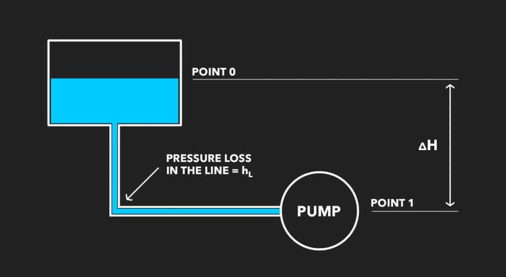
One of the most important fluid mechanic concepts involved in piping systems is net positive suction head (NPSH), a measure of the available pressure on the suction-side of a pump, which is required to prevent cavitation (the formation of vapor bubbles in a fluid) from occurring. This is necessary to determine whether a given pump will operate effectively without experiencing cavitation. Another way of understanding NPSH is that it’s the amount of fluid energy at the pump suction in reference to absolute zero energy.
With centrifugal pumps in particular, it’s also important to understand the net positive suction head required (NPSHr). This metric represents the amount of fluid energy required by the pump to operate without cavitation. Pump manufacturers test their pumps to determine the NPSHr over the range of operating flow rates for the pump.
The amount of fluid energy the piping system provides to the pump suction is called net Positive suction head available (NPSHa). NPSHa is a function of the following characteristics of the piping system on the suction side of the pump:
To prevent cavitation from occurring, the piping system must provide the fluid with enough energy to keep the pressure at the eye from dropping below the fluid’s vapor pressure.
Here is the NPSHa equation:

Here are the key terms you need to know for this equation:
| Ptank | pressure on the liquid surface of the supply tank |
| Patm | local atmospheric pressure (psia) |
| Pvp | vapor pressure of liquid entering the pump section (psia) |
| p | fluid density (lb/ft3) |
| Ztank | elevation of the bottom of the supply tank, measure from the reference plane (ft) |
| ZLevel | liquid level measured from the bottom of the tank (ft) |
| Zpump | elevation of the centerline of the pump section (ft) |
| hL | head loss in the suction pipeline between the tank and the pump section (ft) |
Equations for calculating NPSH vary widely depending on the different characteristics of a piping system. For example, systems where tanks are open to the atmosphere have different fluid mechanics than those that are fully sealed.
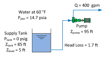
For a tank open to the atmosphere, Ptank in the above equation would be 0 psig. Consider the following system in which water must be lifted from the tank to the pump suction, called a suction lift configuration:

In this example, the NPSHa calculation should go as follows:

As long as the pump’s NPSHr is less than 26.6 feet, the pump should not cavitate. However, there are some suction piping configurations that may cause the pump to cavitate even though NPSHa is greater than NPSHr.
The NPSHa formula can also be used to determine what changes are necessary to create desired fluid conditions. For example, what if you want to create a vacuum within the piping system?
The pump suction pressure in the system from Example 1 would be below atmospheric pressure, or at a vacuum, because the pump must pull the liquid up from the tank, so the change in elevation reduces the fluid pressure.
In addition, the head loss between the tank and pump suction also reduces the fluid’s static pressure, causing the pressure at the pump suction to be at a vacuum. This is an application of the Bernoulli principle in which the pressure head is converted into elevation head, resulting in a reduction in the fluid pressure.
The actual pressure at the pump suction can be calculated by rearranging the Bernoulli equation below to solve for P2:

Making these calculations by hand or on spreadsheets is not only time-consuming, but also incredibly vulnerable to human error, which can set your engineering department back by days. In order to maintain accuracy and improve overall efficiency, it’s critical to invest in a fluid simulation program that handles the math for you.
PIPE-FLO is the engineering standard for modeling and simulation calculations to manage your entire fluid system lifecycle. From design to digital twin simulations, our software is proven to save time and money.

| Cookie | Duration | Description |
|---|---|---|
| __hssc | 30 minutes | HubSpot sets this cookie to keep track of sessions and to determine if HubSpot should increment the session number and timestamps in the __hstc cookie. |
| __hssrc | session | This cookie is set by Hubspot whenever it changes the session cookie. The __hssrc cookie set to 1 indicates that the user has restarted the browser, and if the cookie does not exist, it is assumed to be a new session. |
| _GRECAPTCHA | 5 months 27 days | Google Recaptcha service sets this cookie to identify bots to protect the website against malicious spam attacks. |
| cookielawinfo-checkbox-advertisement | 1 year | Set by the GDPR Cookie Consent plugin, this cookie records the user consent for the cookies in the "Advertisement" category. |
| cookielawinfo-checkbox-analytics | 11 months | This cookie is set by GDPR Cookie Consent plugin. The cookie is used to store the user consent for the cookies in the category "Analytics". |
| cookielawinfo-checkbox-functional | 11 months | The cookie is set by GDPR cookie consent to record the user consent for the cookies in the category "Functional". |
| cookielawinfo-checkbox-necessary | 11 months | This cookie is set by GDPR Cookie Consent plugin. The cookies is used to store the user consent for the cookies in the category "Necessary". |
| cookielawinfo-checkbox-others | 11 months | This cookie is set by GDPR Cookie Consent plugin. The cookie is used to store the user consent for the cookies in the category "Other. |
| cookielawinfo-checkbox-performance | 11 months | This cookie is set by GDPR Cookie Consent plugin. The cookie is used to store the user consent for the cookies in the category "Performance". |
| CookieLawInfoConsent | 1 year | CookieYes sets this cookie to record the default button state of the corresponding category and the status of CCPA. It works only in coordination with the primary cookie. |
| elementor | never | The website's WordPress theme uses this cookie. It allows the website owner to implement or change the website's content in real-time. |
| JSESSIONID | session | New Relic uses this cookie to store a session identifier so that New Relic can monitor session counts for an application. |
| PHPSESSID | session | This cookie is native to PHP applications. The cookie stores and identifies a user's unique session ID to manage user sessions on the website. The cookie is a session cookie and will be deleted when all the browser windows are closed. |
| viewed_cookie_policy | 11 months | The cookie is set by the GDPR Cookie Consent plugin and is used to store whether or not user has consented to the use of cookies. It does not store any personal data. |
| Cookie | Duration | Description |
|---|---|---|
| __cf_bm | 30 minutes | Cloudflare set the cookie to support Cloudflare Bot Management. |
| _icl_visitor_lang_js | 1 day | WPML sets this cookie to store the redirected language. |
| drift_aid | 1 year 1 month 4 days | Drift sets this cookie as a session identifier token. It is used to tie the visitor on your website to a current website session within the Drift system. This enables session-specific features, such as popping up a message only once during a 30 minute session to prevent a disruptive experience. |
| drift_campaign_refresh | 30 minutes | Drift sets this cookie as a unique ID for the specific user. This allows the website to target the user with relevant offers through its chat functionality. |
| driftt_aid | 1 year 1 month 4 days | Drift sets this cookie as an anonymous identifier token. As people come onto the site, they will get this cookie. |
| li_gc | 5 months 27 days | Linkedin set this cookie for storing visitor's consent regarding using cookies for non-essential purposes. |
| lidc | 1 day | LinkedIn sets the lidc cookie to facilitate data center selection. |
| UserMatchHistory | 1 month | LinkedIn sets this cookie for LinkedIn Ads ID syncing. |
| wp-wpml_current_language | session | WordPress multilingual plugin sets this cookie to store the current language/language settings. |
| wpml_browser_redirect_test | session | This cookie is set by WPML WordPress plugin and is used to test if cookies are enabled on the browser. |
| Cookie | Duration | Description |
|---|---|---|
| __lotl | 5 months 27 days | Lucky Orange sets this cookie to identify the traffic source URL of the visitor's original referrer, if any. |
| _lo_uid | 1 year 1 month 4 days | Lucky Orange sets this cookie as a unique identifier for the visitor. |
| _lo_v | 1 year | Lucky Orange sets this cookie to identify the total number of visitor's visits. |
| _lorid | 10 minutes | Lucky Orange sets this cookie to record the current ID of visitors. |
| Cookie | Duration | Description |
|---|---|---|
| __hstc | 5 months 27 days | Hubspot set this main cookie for tracking visitors. It contains the domain, initial timestamp (first visit), last timestamp (last visit), current timestamp (this visit), and session number (increments for each subsequent session). |
| _fbp | 3 months | Facebook sets this cookie to display advertisements when either on Facebook or on a digital platform powered by Facebook advertising after visiting the website. |
| _ga | 1 year 1 month 4 days | Google Analytics sets this cookie to calculate visitor, session and campaign data and track site usage for the site's analytics report. The cookie stores information anonymously and assigns a randomly generated number to recognise unique visitors. |
| _ga_* | 1 year 1 month 4 days | Google Analytics sets this cookie to store and count page views. |
| _gcl_au | 3 months | Google Tag Manager sets the cookie to experiment advertisement efficiency of websites using their services. |
| _gd_session | 4 hours | This cookie is used for collecting information on users visit to the website. It collects data such as total number of visits, average time spent on the website and the pages loaded. |
| _gd_svisitor | 1 year 1 month 4 days | This cookie is set by the Google Analytics. This cookie is used for tracking the signup commissions via affiliate program. |
| _gd_visitor | 1 year 1 month 4 days | This cookie is used for collecting information on the users visit such as number of visits, average time spent on the website and the pages loaded for displaying targeted ads. |
| AnalyticsSyncHistory | 1 month | Linkedin set this cookie to store information about the time a sync took place with the lms_analytics cookie. |
| CONSENT | 2 years | YouTube sets this cookie via embedded YouTube videos and registers anonymous statistical data. |
| hubspotutk | 5 months 27 days | HubSpot sets this cookie to keep track of the visitors to the website. This cookie is passed to HubSpot on form submission and used when deduplicating contacts. |
| ifso_visit_counts | 1 year | If So sets this cookie to store number of visits. |
| ln_or | 1 day | Linkedin sets this cookie to registers statistical data on users' behaviour on the website for internal analytics. |
| vuid | 1 year 1 month 4 days | Vimeo installs this cookie to collect tracking information by setting a unique ID to embed videos on the website. |
| Cookie | Duration | Description |
|---|---|---|
| bcookie | 1 year | LinkedIn sets this cookie from LinkedIn share buttons and ad tags to recognize browser IDs. |
| bscookie | 1 year | LinkedIn sets this cookie to store performed actions on the website. |
| li_sugr | 3 months | LinkedIn sets this cookie to collect user behaviour data to optimise the website and make advertisements on the website more relevant. |
| VISITOR_INFO1_LIVE | 5 months 27 days | YouTube sets this cookie to measure bandwidth, determining whether the user gets the new or old player interface. |
| YSC | session | Youtube sets this cookie to track the views of embedded videos on Youtube pages. |
| yt-remote-connected-devices | never | YouTube sets this cookie to store the user's video preferences using embedded YouTube videos. |
| yt-remote-device-id | never | YouTube sets this cookie to store the user's video preferences using embedded YouTube videos. |
| yt.innertube::nextId | never | YouTube sets this cookie to register a unique ID to store data on what videos from YouTube the user has seen. |
| yt.innertube::requests | never | YouTube sets this cookie to register a unique ID to store data on what videos from YouTube the user has seen. |
| Cookie | Duration | Description |
|---|---|---|
| _an_uid | 7 days | No description available. |
| _gd1687981540406 | session | Description is currently not available. |
| 6suuid | 1 year 1 month 4 days | No description available. |
| ifso_page_visits | 1 year 1 month 4 days | No description available. |
| oribi_cookie_test | session | Description is currently not available. |
| oribili_user_guid | 1 year | Description is currently not available. |